
For your convenience we have placed all specifications and technical drawings for our truncated dome tiles on this page. We have divided these resources by Replaceable Cast in Place tile and Surface Applied tile, although there are some commonalities between the two. Below you will find the colors available for all of our tactile paving, as well as all the different sizes. It is important to note, however, that all of our detectable warning tiles can be cut to fit in any space; this can be done without voiding the Product Warranty.
Every Access® Tile ADA compliant tile is tested rigorously to ensure it is durable and long-lasting, using a series of AASHTO tests, ASTM concrete tests, and ASTM D tests. This information can be found in the characteristics table.
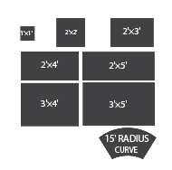
Available Sizes
Available Colors
FED 23594
FED 33538 / RAL 1003
FED 31350
FED 20109 / RAL 8012
FED 22144 / RAL 3016
FED 15187 / RAL 2486
FED 27925
FED 26280
FED 36118 / RAL 2486
FED 17038 / RAL 9005
Replaceable Cast in Place Tiles
Replaceable Cast in Place Specifications
| Part No. | Standard Sizes | Weight | Box Quality | Anchors Included |
|---|---|---|---|---|
| ACC-R-1212-XX | 1' X 1' | 5 lbs. (2 kg) | 10 | 4 |
| ACC-R-2424-XX | 2' X 2' | 9 lbs. (4 kg) | 10 | 9 |
| ACC-R-2436-XX | 2' X 3' | 12 lbs. (5 kg) | 10 | 12 |
| ACC-R-2448-XX | 2' X 4' | 13 lbs. (7 kg) | 10 | 13 |
| ACC-R-2460-XX | 2' X 5' | 18 lbs. (9 kg) | 10 | 18 |
| ACC-R-3648-XX | 3' X 4' | 24 lbs. (11 kg) | 10 | 18 |
| ACC-R-3660-XX | 3' X 5' | 31 lbs. (13 kg) | 10 | 24 |
| ACC-R-3024CRV | 30" X 24" 15' Radius | 10 lbs. (4 kg) | 10 | 9 |
| ACC-R-ANCH | Anchor Assembly | 50 | ||
| BIT-T27 | T-27 tamper Proof Torx® Bit | 5 |
Replaceable Cast in Place Physical Characteristics
| ASTM Reference | Test Description | Test Results |
|---|---|---|
| ASTM D 695 | Compressive Strength | 26,900 |
| ASTM D 790 | Flexural Strength | 31,300 |
| ASTM D 570 | Water Absorption | 0.05% |
| ASTM C 1028 | Slip Resistance | 1.18 Dry / 0.88 wet |
| ASTM E 84 | Flame Spread Index | <= 25 |
| ASTM B 117 | Salt Spray | No Change (300 hours) |
| ASTM 1308 | Chemical Stain | No Effect |
| ASTM C 501 | Abrasion Resistance | lw >500 |
| ASTM G 155 | Accelerated Weathering | Delta E <5 (2,000 hours) |
| ASTM D 638 | Tensile Strength | 12,800 psi |
| AASHTO-H20 | Load Bearing at 10,410 lbs | No Cracking, Delamination or Deformation |
| ASTM C 1026 | Freeze/Thaw/Heat | No Chipping, Cracking, or Peeling |
| ASTM D 1037 | Accelerated Aging (Freeze/Thaw) | No Changing in Color, Gloss or Delamination |
| ASTM D 696-03 | Linear Thermal Expansion | 9.45×10⁻⁷ per ºFahrenheit |
| RCRA-C | Non-Hazardous Classification | Non-Hazardous |
Replaceable Cast in Place Technical drawing
| Product Size | 1'X1' | 2'x2' | 2'x3' | 2'x4' | 2'x5' | 3'x4' | 3'x5' | Radius |
|---|---|---|---|---|---|---|---|---|
 | | | | | | | |
|
| DWG |
Surface Applied Tiles
Surface Applied Specifications
| Part No. | Standard Sizes | Weight | Box Quantity | Anchors |
|---|---|---|---|---|
| ACC-S-1212-XX | 1' X 1' | 2 lbs. (1 kg) | 16 | 4 |
| ACC-S-2424-XX | 2′ X 2' | 8 lbs. (4 kg) | 16 | 6 |
| ACC-S-2436-XX | 2' X 3' | 10 lbs. (5 kg) | 16 | 8 |
| ACC-S-2448-XX | 2′ X 4′ | 13 lbs. (6 kg) | 16 | 8 |
| ACC-S-2460-XX | 2' X 5' | 16 lbs. (7 kg) | 16 | 10 |
| ACC-S-3648-XX | 3′ X 4′ | 20 lbs. (9 kg) | 16 | 12 |
| ACC-S-3660-XX | 3' X 5' | 27 lbs. (12 kg) | 16 | 15 |
| ACC-S-3024-CRV | 30" X 24" 15' Radius | 8 lbs. (4 kg) | 16 | 16 |
| ACC-S-ANCH-XX | Axius® Fasteners | 50 | ||
| TBS-010 | Tactile Bond & Seal | 12 |
Surface applied Physical Characteristics
| ASTM Reference | Test Description | Test Results |
|---|---|---|
| ASTM D 695 | Compressive Strength | 26,900 |
| ASTM D 790 | Flexural Strength | 31,300 |
| ASTM D 570 | Water Absorption | 0.05% |
| ASTM C 1028 | Slip Resistance | 1.18 Dry / 0.88 wet |
| ASTM E 84 | Flame Spread Index | <= 25 |
| ASTM B 117 | Salt Spray | No Change (300 hours) |
| ASTM 1308 | Chemical Stain | No Effect |
| ASTM C 501 | Abrasion Resistance | lw >500 |
| ASTM G 155 | Accelerated Weathering | Delta E <5 (2,000 hours) |
| ASTM D 638 | Tensile Strength | 12,800 psi |
| AASHTO-H20 | Load Bearing at 10,410 lbs | No Cracking,Delamination or Deformation |
| ASTM C 1026 | Freeze/Thaw/Heat | No Chipping, Cracking, or Peeling |
| ASTM D 1037 | Accelerated Aging (Freeze/Thaw) | No Changing in Color, Gloss or Delamination |
| ASTM D 696-03 | Linear Thermal Expansion | 9.45×10⁻⁷ per ºFahrenheit |
| ASTM C 1583 | Tile Bond Strength | Passed |
| RCRA-C | Non-Hazardous Classification | Non-Hazardous |
Surface applied Technical drawing
| Product Size | 1'X1' | 2'x2' | 2'x3' | 2'x4' | 2'x5' | 3'x4' | 3'x5' | Radius |
|---|---|---|---|---|---|---|---|---|
| | | | | | | |
|
| DWG |